info@sumiowater.com

API Separators Sizing

In API Publication 421 Design and Operation of Oil-Water Separators, the sizing procedure for API separators was described. In this article, we look at the method with the keys to achieving “reasonable” dimensions.

What is an API Separator?

An API separator, in simple terms, is nothing more than one or more parallel rectangular tanks that separate free oil from an oily effluent by gravity and that resembles a rectangular channel due to the relationship between its length and width.

Dimensional Design Variables of API Separators

The sizing procedure for API separators consists of obtaining the dimensions L, B, and d and the number of channels, as shown in the figure.

API Separators Sizing Dimensions

  • The variables are:
    Qm = Design flow of the separator in ft3/min
  • L= Length of the separating channel in ft
  • B = Width of the Separating Channel in ft
  • AH = Horizontal or plan area of the channels or basins in ft2
  • AC = Cross-sectional area of channels in ft2
  • AC = dBn

API 421 is based on Stokes’ law to determine the amount of rise of free oil droplets, for which the value of 150 microns (0.015 cm) is the minimum diameter separated in an API pool. The simplified Stokes equation is, then, as follows:

Stokes equation

WHERE:
  • Vt = Rate of rise of the drop in ft/min
  • Sw = Specific gravity of the water at the design temperature
  • So = Specific gravity of the oil at the design temperature
  • μ = Viscosity of oily water at the design temperature in poise

As well, it has been shown (Allen Hazen, 1904) below ideal laminar flow conditions that a drop at the tank inlet will take a time equivalent to the residence time of the effluent in the tank to try to rise from the bottom.

Laminar Flow in API Separators Sizing

Laminar Flow in Rectangular Tank

Clearing the minimum horizontal area is given by:

                     Hazen Equation

Hazen Equation for API Separators Sizing Procedure

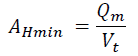
So, API 421 has added a Factor F to account for turbulence and short-circuiting in determining horizontal area:

Hazen Equation Modified for API Separators Sizing Procedure

Necessary Data for the Sizing of API Separators

  • Qm = Design flow in ft3/min
  • T = Design temperature °C / F to determine the properties of the effluent
  • Sw = Specific gravity of oily water at design temperature
  • So = Specific gravity of oil at design
  • temperature
    μ = Viscosity of oily water at the design temperature in poise
TO TAKE INTO CONSIDERATION:
  • The design flow is usually the maximum possible for the case of API separator equipment connected directly to the drainage system. In the case of equipment fed from tanks or compensation lagoons, it is usually the average flow.
  • The temperature governs the sizing of the tank since the viscosity of the wastewater increases with the decrease in temperature and is the most important factor in the equation. The lower the temperature, the lower the ascension speed of the drop, and therefore the tank occupies more area. It is up to the engineer to decide the design temperature, the minimum operating temperature being the most conservative.
ALSO:
  • The difference in density is the driving force for the rise of the drop. The smaller this difference is, the more difficult it will be to separate by gravity. The lighter the oil, the less dense, the easier it will be to separate.
  • Since the specific gravity of water is approximately 1. A specific gravity of 1 for oil would make the buoyancy 0. These limitations allow the separation of crude oil of approx. 10.1º API.

API Separators Sizing Procedure

a. First, obtain the ascent velocity of the drop according to Eq. (1)

b. The horizontal velocity is obtained as follows: Vh = 15 Vt < 3 ft/min

VhyVt

c. If 15 Vt exceeds 3, take 3 ft/min as the maximum value

d. After that, calculate AC the cross-sectional area of the channels in ft

Equation 3 API Separators Sizing Procedure

IMPORTANT:

e. To estimate the minimum number of channels, it assumed that the dimensions of the largest practical channel possible are those with a width B of 20 ft and a depth d of 8 ft. It makes a horizontal area of 160 ft2. Thus, n min = Ac/160. If n is less than 2. Take 1 or 2 as the design value. The API PUB 421 suggests employing n=2 for routine maintenance tasks, avoiding employing the entire separator.

f. Next, choose a channel width B. Remember that if you install a mud sweeper and gimlet mechanism on API equipment, the recommended minimum width for proper installation is 5 ft. Choose a standard channel width which, for American manufacturers, starts at 5′ up to 20′ in 1′ increments.

THEN:

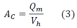
g. Once the width of the channel is selected, obtain d.

Equation 4 API Separators Sizing Procedure

h. At this point, the d/B ratio should be in the accepted value range of 0.3 to 0.5. The value of d calculated by equation (4) will serve as a guide and is the minimum value of d to satisfy the condition of horizontal velocity Vh of equation (3). However, in your best judgment, choose the value of d. Please note that the range accepted for depth values is 3ft. to 8ft. If you add a mud sweeper and gimlet mechanism for a depth of 3 ft, it will be limited to two axes. The usual thing is to use four-axis mechanisms and, to accommodate them, it is necessary to a depth of 5 ft. Two-axle mechanisms also have lower length limits to maintain chain tension and prevent derailment. You should consult the manufacturers when designing between 3′ and 5′ depths.

LAST STEPS

i. Check that the d/B ratio is between 0.3 and 0.5. If not, you must continue playing with the choice of D and B until you meet this condition.

j. Now, calculate the horizontal velocity for the selected dimensions d and B.

Equation 5 API Separators Sizing Procedure

k. With F = Fc Ft, you can calculate the turbulence and short-circuit factors F. The short-circuit factor Fc is assumed to be 1.2, and the turbulence factor is a function of Y = Vh/Vt.

l. In conclusion, the total factor F is from API 421 Figure 4, but you can use the equation below:

Equation 6 API Separators Sizing Procedure

  • The length of the separator is by the following equation: L = F (Vh / Vt) d
  • The minimum ratio L/B is 5. Obtain L/B from the result obtained in 12 and, if it is less than 5, obtain L as L = 5 B

Example

DATA
  • Qm = Design Flow = 110 GPM = 14.7 ft3/min
  • T = Design Temperature º C = 20º
  • Sw = Specific gravity of oily water @T = 0.991
  • So = Specific gravity of the oil @T = 0.857
  • μ = Viscosity of oily water @T =0.01034 poise
CALCULATIONS 

Vt = 0.0241*(0.991-0.8579) / (0.01034) = 0.23 ft/min
Vh = 15 Vt = 3.47 ft/min
Vh > 3. Take 3 ft/min
AC= Qm/Vh = 14.7 / 3 = 4.9 ft2
nmin= AC / 160 = 0.0306 ⇒ n=2

We assume that we are going to install chain and scrapper mechanisms for tank bottom solids and floating scum, and we choose the minimum width

B= 5 ft
dmin= AC / (B n) = 4.9 ft2 / (5 ft x 2) = 0.49 ft.

After that, we choose d = 3.5 ft. D/B = 3.5 / 5 = 0.7.

Since d/B is better than 0.5. We choose B = 7 ft to have a relationship of d/B=0.5
Vh = 14.7 / (7 x 3.5 x 2) = 0.3 ft/min
Y = 0.3 / 0.23 = 1.3, F = 0.005 (1.3)2 + 0.0355 (1.3) + 0.9617 = 1.01
L = F (Vh / Vt) d = 1.01 x 1.3 x 3.5 ft = 4.59 ft.
L/B = 0.66 L= 5 x B = 5 x 7 = 35 ft.
Answer: L= 35ft, B= 7ft, d=3.5ft

Do you want more information?

Scroll to Top